


Unmanned underwater vehicles (UUVs) have been used in marine exploration for several decades, prompting the development of improved control, sensing, and automation systems [1]. These advances, in turn, have opened up the possibility of much wider uses for UUVs, including specialized military operations, such as subsurface sea mine detection and disposal. The breadth of potential applications for these vehicles is likely to grow as the technology continues to advance. However, these increasingly challenging tasks will also require improvements in the power systems used to drive a UUV and its onboard equipment [2].
An ideal UUV would be capable of operating independently on long-range and long-duration missions without recourse to an onshore base facility or support craft. Such a UUV would display low-detectability visible and radar signatures, and be powered by air-independent propulsion to avoid generating detectable acoustic noise when underway. Battery banks are effective sources of power for such propulsion, but without a power source capable of independently recharging, mission duration and distance are limited. Onboard diesel generators require too much space and weight, and the air intake and exhaust ports not only make a UUV vulnerable to visual detection, but also produce acoustic vibration during operation.
The installation of photovoltaic solar panels on top of a UUV could provide a method for air-independent recharging of battery banks. Because solar panels are inherently solid-state systems with no moving parts, they can generate zero acoustic noise while operating. Although solar panels have been demonstrated as a power system for UUVs previously (in conjunction with lithium batteries) [3, 4], these panels must be surfaced and fully above the water line to effectively charge the batteries. An ideal UUV-solar array design could power a UUV without the need to breach the water surface, thus maintaining minimal visual detectability.
Metal-halide perovskite photovoltaic solar cells provide differentially improved performance at converting water-penetrating visible light into usable electric power. Covering the top of a UUV with perovskite solar arrays could (a) power a UUV almost indefinitely; (b) minimize space and weight requirements; (c) maximize mission time to recharge time; and (d) avoid acoustic and visual detectability by providing power with no moving parts.
Underwater, Land, and Space
Most solar technologies have been designed and optimized to work either on land or in outer space. In space, solar cells are exposed to high-energy radiation, and some materials have better radiation hardness than others. Solar radiation in outer space strikes solar panels at a constant spectrum and intensity. Within the atmosphere, solar cells are exposed to a wide variety of regional climates and variable weather.
When exposed to the sun on land, solar cells generally function between 20 and 100 percent of standard AM1.5G solar intensity (“full sunlight” in Figure 1), and the sun radiates at a fairly consistent spectrum (except on overcast days). As a result, current solar cells are optimized to work in a variety of climates and absorb full-spectrum sunlight.
Underwater design considerations are far different. As Figure 1 illustrates, water is a strong filter of both ultraviolet and infrared light. At just 1 m below the surface, only visible light remains; at 10 m underwater, red light is filtered out as well; and at a depth of 100 m, green light is also filtered out (absorption of water is derived from Pegau, Gray, & Zaneveld [5]). A light-emitting diode (LED) shining at 1,000 lux—the high intensity commonly used for product displays in retail stores—is also shown for reference in Figure 1.
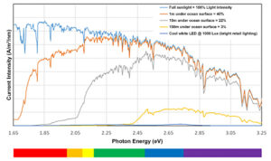
Figure 1. Progression of the underwater spectrum. Below the 1 m depth band, only visible light penetrates.
Underwater solar cells should be optimized for absorbing and converting visible light into electrical energy, and they should be optimized to function at a different light intensity range than terrestrial- or spaced-based arrays. The energy conversion performance of land based solar cells deteriorates rapidly as solar intensity dips below 20 percent of full sunlight. The solar intensity between 1 m and 100 m underwater is just 40 percent to 3 percent of what it is at the surface, presenting a far different design criterion for underwater collection.
The oceans also present a different environmental profile for solar panel operation. Ocean temperatures vary between room temperature (~77 degrees Fahrenheit) and freezing, depending on depth and location. This is a fairly narrow operating range. Solar panels perform better in cool temperatures— one benefit of operating in the cool marine environment. As a result, the main environmental consideration for underwater operation is the corrosiveness of saltwater. This requires a specific packaging design. Therefore, an underwater solar cell should be optimized for (a) visible light, (b) lower light intensities than on land, and (c) resistance to saltwater corrosion.
Solar Power Conversion Efficiency
Solar cells operate with two essential components: a light-absorbing material, and two electrical conductors (wires) to transfer the electricity out of the solar cell. A solar cell is defined by its power conversion efficiency (PCE), which can be described as the power supplied by the device (the current and voltage at the maximum power point, JMPP, VMPP, respectively) divided by the total power available in the incident light.
Another way to define the PCE is as a combination of the open circuit voltage (VOC), the short circuit current (JSC), and the fill factor (FF), which is simply a measure of the squareness of the JV curve, or the extent to which the photocurrent depends on the applied voltage. The secondary definition of PCE can be useful, as it demonstrates the need to increase the open circuit voltage and fill factor in order to boost conversion efficiency and, thus, electrical power output.
![]()
The JSC is directly related to the number of absorbed photons and the quantum efficiency with which they are converted to electricity. It is bounded by the bandgap, or absorption range, of the light-absorbing material. A larger bandgap results in a narrower absorption range. The VOC is also related to the bandgap of the absorbing material, leading to a trade-off between broad absorption and high voltage. A larger bandgap leads to a higher VOC. For land-optimized light absorbers, which take advantage of the wide solar spectrum, the narrow spectrum of visible
light underwater limits their utility. Higher bandgap materials which absorb only the visible spectrum, but give higher VOC, should be used underwater.
A separate problem is the lower solar intensity available underwater and the resultant lower FF. Wafer silicon-based light absorbers are often hampered by material properties and defects that become a problem at low light intensity. These problems manifest as a reduction in both VOC and FF through a process called leakage current or shunt conductance. Leakage current can be conceptualized as water spilling over the sides of a hydroelectric dam: when the turbines are running at full capacity, the leaking water is an inconsequential loss; but, if the turbines were to suddenly operate at 1 percent capacity, there would be as much water leaking out as flowing through the turbines, thus reducing their efficiency. Thin-film solar cells have material and design properties that enable higher performance in low-light environments [6, 7].
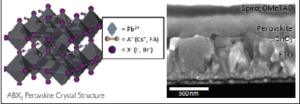
Figure 2. (Left) Crystal structure of a lead halide perovskite. (Right) SEM micrograph showing thin film device architecture.
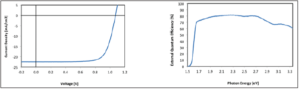
Figure 3. (Left) Current voltage characteristics of a lead halide solar cell. (Right) External quantum efficiency as a function of illumination wavelength.
To optimize the underwater solar cell for visible light, a larger bandgap absorbing material should be used to maximize VOC. To optimize for low light intensity, a thin-film solar cell should be used to minimize leakage current.
Metal-halide Perovskite Solar Cells
Metal-halide perovskite technology has been developing rapidly in university labs for the last several years, and represents a promising approach for the efficient conversion of visible light into electrical power [8, 9]. These materials adopt the perovskite crystal structure and follow the chemical formula ABX3, where A is a cation or mixture of cations— most often Cs+, formamidinium, or methyl ammonium; B is Pb2+; and X represents a halide or a mixture of halides—typically Bror I-. The absorption edge of these materials can fall between 1.55 and 2.25 eV (800–550 nanometers [nm]), and can be tuned via composition, specifically by varying the Brand I- content. The perovskite crystal structure is shown in Figure 2.
A perovskite solar cell is a thin film structure, with the light-absorbing perovskite material measuring around 500 nm thick. The entire structure, with electrical conductors included, is about 1 micron wide—about 1/100th the width of a human hair. Researchers are developing perovskite solar cells for land based solar applications either as a standalone material or paired with commercialized technologies such as silicon to boost their power output.
These laboratory solar cells have lived up to performance expectations, reaching parity with other thin film technologies, both (a) as a standalone material, and (b) in its function as a combination of perovskite and silicon [10, 11].
Tandem PV has developed an advanced perovskite solar cell and tested it in conditions representative of modern indoor lighting, using both LED and fluorescent lights. The spectrum of indoor lighting is not dissimilar to the spectrum underwater, and the intensity of lighting indoors is also similar to the light level found hundreds of meters underwater (see Figure 1).
In tests of indoor lighting conditions, the perovskite solar cell has demonstrated a conversion efficiency of 25 to 30 percent when placed underneath a white LED at intensities relevant to underwater operation (see Figure 4). This technology has a theoretical efficiency limit of nearly 50 percent under a visible spectrum.
An important example of the difference between silicon and perovskite solar cells can be seen in Table 1. Silicon converts full sunlight into electricity at about the same efficiency it does visible light, but its overall power production range falls sharply once only visible light is available. Perovskite solar cells are far better at converting visible light into usable energy, producing nearly the same power 1 m underwater as on land. The power generation differences between the two technologies only increase as the water depth increases, and light intensity decreases.
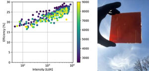
Figure 4. (Left) Efficiency of Tandem PV’s perovskite solar technology as a function of light intensity
and color temperature of the illumination source (indicated by the color bar, in degrees Kelvin). For reference, the light intensity at a depth of 100 m on the lux scale would be around 10,000 lux. (Right) Photo of a Tandem PV perovskite cell.
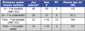
Table 1. Expected solar cell parameters for generic silicon and lead halide perovskite devices in direct sunlight and calculated for 1 m under the surface of the ocean.
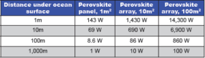
Table 2. Expected peak power output of perovskite solar arrays depending on coverage area and water depth. Calculated based off Tandem PV solar cell results under simulated light.
Perovskites as Power Sources for UUVs
On a UUV, the top surface of the submersible can be oriented to constantly face the sun. Typically, around six hours of sunlight are available every day for peak solar power production. Depending on the power requirements of the submersible, daylight hours can be used for recharging, while night hours are used for missions. If power requirements are easily met, missions can be run during daylight hours as well, with the solar panels generating power while underway.
The expected peak power output of a perovskite solar array on top of a UUV as a function of coverage area and water depth is presented in Table 2. As long as the sun is shining, an appreciable amount of power is likely to be generated by the solar panels even if submerged to a depth of 100 m (see Table 2). Further determination of operation duty cycle (mission time vs. recharge time) is pending an engineering investigation of power needs, surface area available, and water depth of missions and recharging depth.
Unlike other electricity generation sources such as diesel and fuel cells, no fuel is stored or consumed by solar panels, enabling indefinite UUV missions without the need to return for refueling. Removing the need to carry fuel on board creates space and weight savings that can be used for other purposes such as additional sensing and communication equipment.
Conclusion
Metal-halide perovskite solar cells are uniquely well-suited to convert light into electrical power in a marine environment. Continued improvements in manufacturing protocols and device design will push the power density of this technology even higher. While there is limited publicly available information on UUVs and power requirements, one example is the solar-powered autonomous underwater vehicle (SAUV) from Falmouth Scientific [12]; when outfitted with 1 m2 of silicon-based solar panels, this small craft can operate indefinitely, but it requires resurfacing and recharging during daylight hours.
Perovskite solar panels, on the other hand, may allow such a craft to operate continuously without refueling, recharging, or surfacing. Solar technologies have additional advantages over traditional fuel sources as they require no moving parts and are air independent, to avoid detectable acoustic noise.
Further development of perovskite solar cells for underwater applications should involve field testing of perovskite cells underwater at various depths; engineering of packaging for the solar cells compatible with long-term ocean use; a study of the power requirements for UUVs and the anticipated energy generated by the solar panels during missions; and design of the perovskite solar array to conform to UUV shape, size, and weight requirements.
Acknowledgements
This work was partially funded by a small business innovation research grant from the National Science Foundation, and performed in collaboration with the Joint Center for Artificial Photosynthesis at the Lawrence Berkeley National Laboratory.
References
1. Gafurov, S. A., & Klochkov, E. V. (2015). Autonomous unmanned underwater vehicles development tendencies. Procedia Engineering, 106, 141–148. doi:10.1016/j.proeng.2015.06.017
2. Wang, X., Shang, J., Luo, Z., Tang L., Zhang, X., & Li, J. (2012). Reviews of power systems and environmental energy conversion for unmanned underwater vehicles. Renewable and Sustainable Energy Reviews, 16(4), 1958–1970. doi:10.1016/j.rser.2011.12.016
3. Jalbert, J., Baker, J., Duchesney, J., Pietryka, P., Dalton, W., Blidberg, D. R., . . . Holappa, K. (2003). A solar-powered autonomous underwater vehicle. Oceans 2003. Celebrating the Past… Teaming Toward the Future (IEEE Cat. No.03CH37492). doi:10.1109/ OCEANS.2003.178503
4. Crimmins, D. M., Patty, C. T., Beliard, M. A., Baker, J., Jalbert, J. C., Komerska, R. J., . . . Blidberg, D. R. (2006, October). Long-endurance test results of the solar- powered AUV system. Oceans 2006. doi:10.1109/OCEANS.2006.306997
5. Pegau, W. S., Gray, D., & Zaneveld, J. R. V. (1997). Absorption and attenuation of visible and near-infrared light in water: Dependence on temperature and salinity.” Applied Optics, 36(24), 6035–6046. doi:10.1364/AO.36.006035
6. Kasemann, M., Rühle, K., & Reindl, L. M. (2013, September). Photovoltaic energy harvesting under low lighting conditions. Paper presented at the AMA Conferences 2013, Nürnberg, DE. doi:10.5162/sensor2013/C8.3
7. Rasheduzzaman, M., Balakrishna Pillai, P., Mendoza, A. N. C., & De Souza, M. M. (2016). A study of the performance of solar cells for indoor autonomous wireless sensors. 2016 10th International Symposium on Communication Systems, Networks and Digital Signal Processing (CSNDSP). doi:10.1109/CSNDSP.2016.7574001
8. Smardzewski, R. (2015, April). Perovskite solar cells. Journal of the Homeland Defense & Security Information Analysis Center, 2(1), 3–6. Retrieved from https://www.hdiac.org/wp-content/
uploads/2018/04/HDIAC-Journal_Volume-2-Issue-1.pdf
9. Correa-Baena, J-P., Abate, A., Saliba, M., Tress, W., Jacobsson, T. J., Grätzel, M., & Hagfeldt, A. (2017). The rapid evolution of highly efficient perovskite solar cells. Energy & Environmental Science, 10(3),710–727. doi:10.1039/C6EE03397K
10. Green, M. A., Hishikawa, Y., Dunlop, E. D., Levi, D. H., Hohl-Ebinger, J., & Ho-Baillie, A. W. Y. (2018, June). Solar cell efficiency tables (version 52). Progress in Photovoltaics: Research and Applications, 26, 427–436. doi:10.1002/pip.3040
11. Osborne, M. (2018, June 25). Oxfor PV takes record perovskite tandem solar cell to 27.3% conversion efficiency. PV-Tech. Retrieved from https://www.pv-tech.org/news/oxford-pv-takes-record-perovskitetandem-solar-cell-to-27.3-conversion-effi
12. Falmouth Scientific, Inc. (2009, August).FSI SAUV II Specifications: Solar powered autonomous underwater vehicle, long-endurance AUV. Retrieved from http://www.falmouth.com/images/SAUVRev1. pdf