


“U.S. Army Research Laboratories and the Massachusetts Institute of Technology (MIT) Lincoln Laboratory have developed a new draft standard called Tactical Microgrid Standard (TMS). Schweitzer Engineering Laboratories, Inc. (SEL) was hired to validate the specification by building a prototype TMS microgrid system. SEL teams blended proven powerMAX® control and protection methods with the TMS standard, the result of which is a new level of safe, reliable, and economic power systems. This article describes how TMS systems automatically configure a microgrid protection and control system without human involvement. Two variants of this solution are shared: one for a rapidly deployed, mobile power system, and one for a fixed garrison facility. The article concludes with a summary of proven supply chain security methods.”
Introduction
Electric power is essential to our modern society and in U.S. Department of Defense (DoD) facilities. The short-term effects of no power are no heat, lights, defense systems, or communications. Longer-term effects are no fresh water, no sewage treatment, and spoiled food.
This article reviews a significant improvement in technology to provide safer and more reliable, resilient, and economic delivery of electric power to DoD facilities worldwide. This technology has been praised by the U.S. Department of Energy [1] [2] and independent researchers [3], and it has received an international award [4].
The technology outlined in this article is a large step forward in reliable power delivery for the DoD and offers the following benefits:
- There is no single point of failure.
- The systems reduce fuel consumption up to 73 percent.
- They have a plug-and-play configuration, which requires limited training to configure or operate.
- They are Tactical Microgrid Standard (TMS)-compliant.
- They are designed to meet risk management framework (RMF) cybersecurity control policies.
- They allow interoperability with all makes, models, and sizes of military and commercial off-the-shelf (COTS) generators.
- They mitigate the accumulation of unburned hydrocarbon residue in the exhaust system, known as wet stacking, and the need for corresponding maintenance.
- All controllers are identical, making parts easily interchangeable.
- They allow load sharing and interoperation with any proprietary generator or inverter.
- The electronics meet NERC CIP, RMF, NIST, and ISA 99 security requirements.
- The control method allows generator sets (gensets) to be geographically dispersed to improve power resiliency.
The Challenge
The problems of the latest-generation power systems deployed by the U.S. armed forces today make for a fragile power system. These challenges are addressed with the technology described in this article.
Military acquisition is locked into a specific genset brand and model for an entire fleet, creating cost overruns and single-manufacturer vulnerabilities. This lock is caused by genset manufacturers because their technology does not interoperate with the technology of other genset manufacturers. Dissimilar or mismatched gensets and inverters must be capable of working in parallel for a resilient acquisition program. Inverters are required for batteries and photovoltaic (PV) sources to connect to a microgrid.
Gensets are oversized to guarantee full rated power in harsh environments. Oversized gensets are not optimized for low-load conditions, creating many problems. These problems, including fuel waste, increased emissions, and engine damage, shorten mission effectiveness due to excessive fuel consumption and endanger lives in the transportation of excessive fuel. Oversized gensets require the transportation of additional fuel to the battlefield and prematurely destroy the engines with wet stacking.
Interoperability is not possible with present equipment being procured by the DoD. All genset manufacturers use a proprietary isochronous (ISO) engine load-sharing system, thereby preventing interoperability. ISO load-sharing techniques require high-speed communications between gensets to stabilize the inherently unstable ISO control mode. Without this high-speed link, gensets have frequency and voltage instabilities and will trip offline. North American utilities do not allow these control techniques on the bulk electric power system because they are inherently destabilizing, impractical to maintain, unreliable, and do not allow interoperation between diverse manufacturer gensets.
Conventional gensets use outdated proportional integral derivative (PID) control loop techniques. When paralleled with inverters or electronic loads, PID controls commonly cause frequency and voltage instabilities [5], high fuel usage, and high emissions.
Co-located generators, especially the load-sharing lines between gensets, are a primary target for adversaries. Conventional load-sharing communications lines cannot transmit farther than a few meters, requiring that all paralleled gensets be co-located. Note that load-sharing lines are not required on the bulk electric power system because of its superior design.
The systems deployed by the U.S. armed forces today are too complicated. Many genset operators are not electric power system experts, nor can they be. Their expertise lies with other military tasks. This discrepancy, combined with a great number of technology overcomplexities, makes it time-consuming and expensive to configure a reliable forward operating base. Only the most simplistic and inefficient designs are typically achievable without assistance from outside a unit. Equipment specifications, site designs, field installation, repairs, and field commissioning require that specialists spend significant time traveling and in the field, often putting the DoD’s limited talent pool in harm’s way. This reduces the practicality of a rapidly mobile forward operating base.
Cybersecurity challenges for legacy DoD communications systems include open protocols, managed switches, nonsecure ports, and the logistical difficulties that come with operating system maintenance and malware and software updates.
Cooperative Research and Development
The U.S. Army Corps of Engineers Construction Engineering Research Laboratory (CERL), the U.S. Army Combat Capabilities Development Command (C5ISR), and MIT Lincoln Laboratory developed the TMS interoperable communications system standard. Schweitzer Engineering Laboratories, Inc. (SEL) was hired by the DoD to validate the TMS specification by building a prototype TMS microgrid system. During this project, SEL simultaneously self-funded (cost-shared) the research and development (R&D) to solve a great number of additional DoD mobile power problems not directly addressed by TMS. SEL’s project demonstrated successful technology transfer from the DoD, improved the maturing TMS documentation, and proved interoperability to be practical.
SEL power system experts determined the root cause of each of the aforementioned challenges and designed a safe, reliable, low-cost solution. This was accomplished by blending gigawatt-scale utility and industrial controls and protection methods [6] with the TMS standard [7]. The system SEL developed has no single point of failure, does not lock the acquisition into a single manufacturer, does not depend on antiquated PID control methods, allows for geographic dispersal of the gensets, allows for minimally sized and highly efficient gensets from multiple manufacturers to interoperate, and provides superior grid power system resiliency, reliability, and power quality.
The SEL system is simple to operate; high school interns have successfully set up, operated, and performed failure recovery of a 440 kW power system comprised of eight gensets from four different manufacturers (TQG, CAT, Taylor, and Gillette). The cybersecurity posture of the systems is also improved and simplified, and all electronics are sourced from U.S. manufacturers.
This work is a testament to the power of linking industrial power and cybersecurity experts with DoD research facilities. These efforts have recently been recognized with a significant award [4]. The R&D100 awards committee selected TMS for this award over several other industry standards after analysis of the benefits. The award summary identified the technology as unlocking many opportunities for the DoD, accelerating the acquisition and fielding of advanced technology, and providing faster and more resilient field operations.
The result of these cooperative efforts is a power delivery system with superior resilience. This resiliency improves power system quality and reliability. Reliability is objectively measured in the electric utility industry by outage time with parameters such as the System Average Interruption Duration Index (SAIDI) and System Average Interruption Frequency Index (SAIFI).
Communications Interoperability
TMS specifications call for an interoperable communications structure layered upon the proven Data Distribution Service (DDS) protocol. DDS is a publish/subscribe protocol that uses User Datagram Protocol (UDP) messaging between controllers. DDS has been used by the DoD for over a decade for mission-critical applications.
The TMS roles are as follows:
- Microgrid controller (MC)—sends configuration settings and commands to other TMS-compliant devices.
- Source power device (SRC)—gensets or other power-providing distributed energy resources (DERs).
- Storage power device (STOR)—battery systems that store power.
- Distribution power device (DIST)—power distribution hardware that contains cabling and circuit breakers.
The TMS standard calls for a fixed message set (data structure) for each of these roles. This facilitates interoperable communication between all manufacturers.
Every device on the TMS network is assigned one of these TMS roles. Communication between each device is automated based on device roles and requires no human configuration. For example, as an authorized SRC (genset) is connected to the TMS local-area network (LAN), the SRC role provides a device announcement to the network. In this example, the MC automatically subscribes to the SRC and starts communication of metering and control signaling information. The MC sends configuration parameters to the SRC, thus facilitating acceptance on the microgrid with a known parameterization and control method.
Mobile Microgrids
Rapidly deployed, mobile power systems without connections to a bulk electric power system are commonly powered by diesel reciprocating engine gensets. These mobile power systems are designed for forward operating bases and disaster relief.
In the SEL design, all controllers are identical and only require that their role be specified prior to operation with a control (DIP) switch. Identical controllers are employed to minimize the spare parts inventory requirements and are not required for interoperability. Once the role is specified, the electronics automatically configure all communications, controls, and protection for an entire power system. There is no software required to configure these systems.
Dispatch is accomplished via a microgrid controller, which dispatches all generator sources (SRCs). In the SEL design, there are five modes for the operator to select:
- Rapid stop (shutdown mode). This stops all power sources (gensets) for a rapid demobilization of the facility.
- Normal resiliency (equal percentage load sharing). These controls ensure nominal frequency and voltage are maintained and that watts and volt-amperes reactive (VAR) are shared between gensets of any size or from any manufacturer.
- Optimal fuel usage (start/stop control). These controls temporarily suspend operation of unnecessary gensets, allowing the remainder of gensets to operate at a higher efficiency. Testing has proven that fuel usage is reduced between 10 and 73 percent by employing these methods.
- Optimal resilience mode (emergency mode). This brings all gensets online for the maximum durability of the power system, ensuring that destruction of one or more gensets does not compromise the flow of reliable, high-quality power to the loads. Basic physics identifies that optimal resiliency and optimal fuel usage modes are mutually exclusive. They cannot happen simultaneously, so the user must select which mode they desire depending on site conditions.
- Maintenance mode (wet-stacking mitigation mode). This mode is used to de-foul the engines one at a time. This is achieved through modifications to the power dispatch plan and does not require the addition of load banks or isolation of the generator undergoing wet-stack mitigation activities.These simplified controls are sufficient to control power systems from several megawatts down to a few kilowatts in scale, making them ideal for expeditionary warfare and emergency response teams.
Fig. 1 shows a Mobile Electric Power (MEP) 806B TQG upgraded with energy packet controls and TMS communications. TQGs with the controls upgrade shown in Fig. 1 parallel and seamlessly share load with any genset, battery, photovoltaic (PV) installation, or wind turbine, old or new. Reference [8] provides more details. This older TQG technology procured by the DoD can be modified in less than 30 minutes with TMS technology to interoperate with gensets, inverters, or host nation interconnects of all sizes and from all manufacturers.

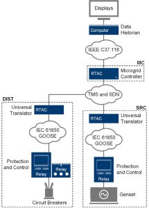
Real-time automation controllers (RTACs) were used as universal translators (protocol gateways) between SRC, MC, and DIST per the predefined TMS data structures. They also provide firewalled security and a physical network isolation barrier between the TMS LAN and the communication within an SRC, MC, or DIST. The architecture is shown in Fig. 2.
Situational Awareness
Time-synchronized, condition-monitoring systems are provided on a single heads-up display; this system records historical data for over 20 years of continuous runtime of the microgrid. Network traffic, cooling water temperatures, oil pressures, power values, frequencies, voltages, reactive power, phase angles, and machine wet-stack fouling are displayed on the single display shown in Fig. 3.
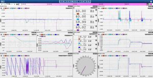
This single display provides predictive, condition-based maintenance indicators, which alert operators to potentially hazardous situations before they become a danger.
Energy Packet Control
One of the more challenging problems to solve has been PID and ISO load-sharing control methods. All reciprocating gensets manufactured today use PID and ISO methods.
The oil and gas industry and utilities have discovered that ISO techniques are inadequate. In fact, these larger, more reliable power systems have standards that specifically forbid ISO control in the interconnect contracts that power producers must follow.
ISO parallel controls require high-speed controls, signaling between gensets, and geographically close generators. These methods are known to fail to interoperate between manufacturers, to have serious frequency and voltage instability modes for modern electronic loads, and to not play well with renewable energy sources, batteries with inverters, and power electronic loads (e.g., data centers).
PID controls are inherently dependent on inertia, i.e., the rotating mass of the gensets and loads. As the loads become primarily power electronic, these PID control methods are proven to destabilize the power system [5].
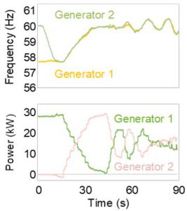
Fig. 4 shows two 30 kW synchronized (paralleled) gensets sharing load using conventional small-network techniques. These units use the conventional PID control method for ISO parallel controls. Note the oscillation (hunting) in power (kW) and frequency. This hunting wastes fuel, reduces engine life, and is precariously close to tripping off the gensets (this is not resilient power system behavior).
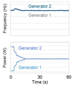
Energy packet controls are the preferred alternative to inertia dependence, PID control, ISO paralleling methods, and power electronic loads (synonymous with –R loads or P/Q loads). Those same two gensets under energy packet controls are shown in Fig. 5 in the same parallel load-sharing scenario. This is resilient power system behavior.
Energy packet control methods do not require a human to tune the controllers. They are faster to configure, and all gensets can be factory set with a guarantee of interoperability with any other manufacturer’s gensets, inverter, or host nation country.
Energy packet controls have a reduced dependence on inertia and, thus, no retuning requirement as power systems are assembled and reassembled. Inertia, load compositions, and impedances can change dramatically without impact on the power system. Engines with energy packet controls can be geographically distributed. These methods have been proven and are on display in live demonstrations [9].
Cybersecurity Underlayment
SEL applied a cybersecurity underlayment to secure the TMS-based solutions. After examining conventional network security approaches, SEL chose a design that uses three components: RTACs, protective relays, and operational technology software-defined networking (OT SDN) Ethernet switches (shown in Fig. 6). This is a proven, practical solution [10].
Multifunction relays and RTACs are architecturally different. Relays operate with an embedded environment that includes safeguards to detect alteration of programming and prevent malware infection or other corruption. RTACs use an embedded operating system that whitelists applications at the kernel level to prevent alteration. This equipment is used in power system utility substations around the world and is commonly part of NERC CIP-certified substation designs at mission-critical facilities [12].
OT SDN underlayment technology is used to lock down the network and to identify intrusions. OT SDN is essential for securing the TMS publish-subscribe network. For a fraction of the cost and complexity of conventional solutions, this system provides a simple and effective networking solution. In the 2017 worldwide microgrid shootout sponsored by the Department of Energy (DOE) National Renewable Energy Laboratory (NREL) [1] [2], the NREL cyber red team was not able to gain entrance to an SDN network. This has been verified multiple times by DoD red teams. SEL OT SDN underlayment technology is designed to obsolete Ethernet network military attack toolkits [12].
OT SDN complements TMS with preconfigured routing circuits that are programmed instead of the self-configured rerouting used in conventional IT networking methods such as Rapid Spanning Tree Protocol (RSTP). OT SDN limits the spread of threats, improves situational awareness, has native intrusion detection, identifies and quarantines threats, and seamlessly reroutes traffic after failures.
OT SDN is different than the IT SDN used by IT departments or data centers. OT SDN is designed to be a low-cost, small form-factor, rugged solution and is locked down after a one-time configuration. OT SDN has much lower latency and jitter than traditional networking, as required by protection and control equipment. OT SDN is tailored to the industrial control system (ICS) environment.
Cybersecurity teams provide operators supporting authorization to operate (ATO) documentation such as the RMF Plan of Action and Milestones (POA&M). The POA&M is a key document in the security authorization package and for continuous monitoring activities of a microgrid. Teams provide a security assessment or vulnerability scan for the delivered solutions; results of that scan are checked against NIST SP800-53A and DISA STIGs. Findings are placed in a POA&M and delivered to the customer. Teams continuously work to remediate any vulnerabilities found and to ensure the delivered solution follows required standards.
Garrison Microgrids
Garrison (campus) microgrids benefit from the TMS communication, SDN security, and microgrid control solutions developed in the oil and gas industry. These designs provide the improved resilience, reduced fuel usage, cybersecurity, simplicity, power quality improvements, and easy scaling of mobile microgrids.
TMS-based garrison systems are slightly different from the mobile solution in that they are designed to retrofit existing onsite backup power gensets and switchgear to quickly convert an existing garrison facility into a microgrid.
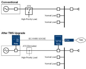
Fig. 6 shows how to retrofit an automatic transfer switch (ATS) to a TMS genset to power a garrison microgrid. In this retrofit, the ATS is eliminated and existing circuit breakers at the genset and the switchgear are controlled by two intelligent multifunction relays. This allows an emergency genset to power a microgrid.
In this solution, the microgrid is isolated from a bulk electric power system (host nation country) by a multifunction relay and circuit breaker at the point of common coupling (PCC) with the bulk electric power system (not shown in figure). The PCC relay provides seamless islanding and compliance to IEEE 2030.7, IEEE 2030.8, and IEEE 1547 [13] [14] [15].
SEL TMS garrison systems are designed for incremental procurement. Gensets and ATS equipment can be retrofitted one device at a time; usually, systems can be retrofitted with a single one-day outage. This allows a crew to economically scale up a facility one generator at a time, minimizes technology adoption risks, and allows purchase of the upgrades in small, affordable increments.
Parris Island Microgrid
The U.S. Marine Corps (USMC) Recruit Depot Parris Island microgrid project in South Carolina was a collaboration between the USMC, Ameresco, and SEL. In addition to substantial site upgrades, the facility proved interoperability between PV, batteries, turbines, and reciprocating diesel gensets.
Because TMS does not yet fully define the inverter, PV, or battery interfaces, this project used the TMS controller constructs but not the protocol implementation. The results are still remarkable.
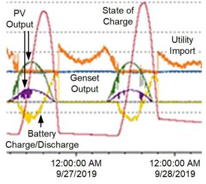
The plot in Fig. 7 shows a day in the life of the Parris Island microgrid. Green and purple are the megawatt output of two PV fields, yellow is the megawatt charge/discharge of a battery-backed inverter (energy storage), red is the state of charge of the battery, blue is the output from a site turbine, and orange is the utility import megawatts. The battery system stores excessive energy from the PV output, lessening the evening load. The turbine stays on baseload unless a major upset occurs. The PV, turbine, and battery system work together to reduce utility charges.
Notwithstanding the success at Parris Island, as with any new technology, the TMS standard has room for improvement. The TMS specification needs enhancement, and further projects must be completed before TMS is formally adopted as a military standard (MIL-STD).
The Parris Island project is the first of many that will be incrementally adopting TMS technology. Only through commercial adoption and more projects can the standard be thoroughly vetted.
Resilient Procurement
The Parris Island microgrid project used resilient procurement methods similar to those practiced for decades by the oil and gas industry and utility power systems.
The USMC specified that best-in-class electronics (the brains of the power system) be embedded into third-party, low-cost switchgear, transformers, reclosers, distribution gear, etc. This means that mission-critical electronics, software, networking equipment, inverters, controllers, and protection relays are sourced from trusted U.S. manufacturers. Switchgear, transformers, cables, engines, and generators (also known as commoditized assets comprised of copper and steel) are safely and economically procured.
Proven Technology
SEL powerMAX garrison and mobile solutions are the merger of the TMS standard and SEL’s long-standing powerMAX Power Management and Control Systems. Each of the points in Fig. 8 represents a completed powerMAX project. The x-axis is the amount of onsite generation on each microgrid.
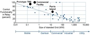
The y-axis is the percent of control functionality performed in protective relays. One hundred percent means all functionality is completed in the relays; 0 percent means all functionality is performed in a centralized RTAC.
This scatter plot shows that smaller power systems are predominately controlled by protective relays. Larger power systems involving more relays require a comprehensive central microgrid controller [16] [17] [18].
Security From the Ground Up
Multifunction protective relays are the primary control, protection, and automation devices used in the U.S. transmission, generation, and distribution stations of America’s bulk electric grid. U.S. utilities strongly prefer relays invented, researched, developed, manufactured, assembled, tested, and supported in the USA [19]. Manufacturers must have a culture of cybersecurity rooted in the concepts of least privilege, need-to-know, and defense-in-depth. Access to manufacturing facilities must be tightly controlled, and 24/7 security must monitor all buildings and access.
The design of multifunction relay hardware, firmware, and supporting software must be subjected to a rigorous peer-review process to ensure the products correctly satisfy customer needs, do not include unnecessary features, and are as simple as possible to use.
A thorough product testing regimen is exhaustive. Threat model analysis is used to review full system architecture. All source code must be reviewed for correctness of function and implementation, then subjected to automated and manual testing designed to detect errors that could result in malfunction or vulnerability. Automated code inspection is used to augment peer code reviews. Version control ensures that all source code, specification documents, and drawings are maintained in a secure, access-controlled repository.
Unit testing ensures that all code modules are exercised and satisfy the design specification. Functional tests are performed on the product or system by automated tools and human testers to verify that it performs as expected on a function-by-function basis. Negative testing, one of which is fuzz testing, is used to prove that the system does not misoperate. For example, deliberately distorted data is sent to external interfaces, trying to induce an error condition. Commercial vulnerability scanning tools are also used to test mission-critical products. Validation testing ensures that the product functions as intended in realistic use cases.
Software is digitally signed using an extended validation code-signing certificate with a key securely held in a hardware security module. Firmware can be authenticated by comparison with a reference hash value available from the manufacturer.
When a manufacturer identifies a defect in a product that could cause a misoperation, failure, or vulnerability, customers should be quickly notified with a service bulletin, which describes the problem, risk to the customer, and mitigation steps.
Supply Chain Security
Manufacturers of mission-critical electronics must embed supply chain security in their principles of operation. Suppliers must be viewed as part of the manufacturing process and educated in the mission, values, and processes of a manufacturer.
An essential step in ensuring supply chain security (cyber and otherwise) and quality is to form lasting, collaborative relationships with each supplier [20]. Manufacturers should clearly communicate their expectations, while at the same time cultivating a commitment to the success of the supplier. Forming strategic relationships results in wins for all parties. A successful supplier selection process requires input from R&D, quality, purchasing, and security teams, ensuring that every supplier and component is vetted from different perspectives.
Manufacturers should use a trust-but-verify approach to conduct onsite audits of suppliers to verify that security safeguards and quality processes conform to their own understanding and expectations, and to better understand risks to supplier business models. Supplier assessment and monitoring is continuous and extends to cybersecurity and financial health.
It is essential to maintain a detailed record of every product manufactured. Recording where each product is installed allows a manufacturer to rapidly notify customers about potential quality or security concerns. Product serial number, firmware, and subassemblies must be tracked. Manufacturers must know who built a product, when it was built, which plant built it, what assembly lines it was built on, and what test station was used. Manufacturers must track who bought it, the identity of the end user, how it was shipped, and who is supporting the product.
A warranty program can be used to improve supplier quality. A long warranty period guaranteeing repair or replacement for the life of a product provides an incentive for customers to return products when they fail. Returned products are analyzed by product experts until root cause is identified, allowing R&D and manufacturing teams to constantly improve designs.
Manufacturers must ensure every critical subcomponent can be sourced from at least two vetted suppliers. Components must be obtained from U.S. suppliers whenever feasible. Suppliers subject to control by potential geopolitical adversaries must be avoided. All software must be created internally, providing a quality control advantage along with the ability to make rapid fixes and enhancements. Vertical integration enhances oversight and custody of products, from R&D design through the complete manufacturing process. This control mitigates the chances of malicious code or components making their way into mission-critical products.
Suppliers must autonomously and continuously scan the threat landscape outside their own company. A devoted 24/7 security operations center, in concert with a business intelligence unit, works to enhance security. These teams must scour an array of public and private threat and other intelligence streams to detect cybersecurity or physical threats to supply chains and internal infrastructure.
Conclusion
The result of these cooperative R&D efforts is a power delivery system with superior resilience, lower fuel usage, less emissions, interoperability with renewables and batteries that is simple to set up, operate, and maintain.
TMS-compliant mobile and garrison microgrid systems can be acquired from SEL today. These SEL systems are designed to update older gensets and switchgear with the latest TMS technology. Users can upgrade their existing onsite gensets in small, affordable increments.
Acknowledgment
SEL acknowledges the U.S. Army Corps of Engineers Construction Engineering Research Laboratory (CERL), the U.S. Army Combat Capabilities Development Command (C5ISR), and MIT Lincoln Laboratory for their close cooperation.
References
- NREL, “Unique Procurement Process Expands Microgrid Research Capabilities at the ESIF,” February 2019. Available: https://www.nrel.gov/news/program/2018/procurement-expands-microgrid-research-capabilities-at-esif.html
- SEL, “NREL Selects SEL Microgrid Controller for the Energy Systems Integration Facility,” August 2018. Available: selinc.com.
- “Navigant Research Leaderboard: Microgrid Controls – Assessment of Strategy and Execution for 15 Microgrid Controller Vendors,” 2018. Available: https://www.navigantresearch.com/reports/navigant-research-leaderboard-microgrid-controls.
- MIT Lincoln Laboratory, “Ten Lincoln Laboratory Technologies Earn 2019 R&D 100 Awards,” November 2019. Available: https://www.ll.mit.edu/news/ten-lincoln-laboratory-technologies-earn-2019-rd-100-awards.
- S. Manson, B. Kennedy, and M. Checksfield, “Solving Turbine Governor Instability at Low-Load Conditions,” proceedings of the 2015 IEEE Petroleum and Chemical Industry Technical Conference, Houston, TX, October 2015.
- “Microgrid System Design, Control, and Modeling Challenges and Solutions Webinar,” June 2019. Available: https://selinc.com/events/on-demand-webinar/126002/.
- Department of Defense Interface Standard TMS, Tactical Microgrid Standard, February 2017.
- Tactical Microgrid Explainer Video. Available: https://selinc.com/solutions/microgrids/.
- SEL powerMAX for Mobile Microgrids trailer demonstration. Available: https://selinc.com/solutions/microgrids/.
- S. Manson and D. Anderson, “Practical Cybersecurity for Protection and Control System Communications Networks,” proceedings of the 2017 Petroleum and Chemical Industry Technical Conference (PCIC), Calgary, AB, Canada, September 2017.
- North American Electric Reliability Corporation Critical Infrastructure Protection (NERC CIP) standards. Available: nerc.com.
- Pacific Northwest National Laboratory and U.S. Department of Energy, “Expanding the Impact of DOE Technology for Energy Cybersecurity.” Available: https://selinc.com/api/download/124796/.
- IEEE 2030.7, IEEE Standard for the Specification of Microgrid Controllers.
- IEEE 2030.8, IEEE Standard for the Testing of Microgrid Controllers.
- IEEE 1547, IEEE Standard for Interconnection and Interoperability of Distributed Energy Resources With Associated Electric Power System Interfaces.
- K. G. Ravikumar, S. K. Raghupathula, and S. Manson, “Complete Power Management System for an Industrial Refinery,” proceedings of the 2015 IEEE Petroleum and Chemical Industry Technical Conference, Houston, TX, October 2015.
- E. Roy Hamilton, J. Undrill, P. S. Hamer, and S. Manson, “Considerations for Generation in an Islanded Operation,” IEEE Transactions on Industry Applications, Vol. 46, Issue 6, Nov.-Dec. 2010.
- S. Manson, K. G. Ravikumar, and S. K. Raghupathula, “Microgrid Systems: Design, Control Functions, Modeling, and Field Experience,” proceedings of the 2018 Grid of the Future Symposium, Reston, VA, October 2018.
- Newton-Evans, “Worldwide Study of the Protective Relay Marketplace in Electric Utilities: 2019-2022.” Available: newton-evans.com.
- SEL, “Securing Your Supply Chain: Best Practices From SEL,” Available: selinc.com.